MASS Modules: Shear Wall
Design Multi-Storey Shear Walls or Single Storey Full Elevations
Shear Wall Element
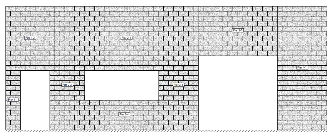
Single Storey Elevation - Shearline
Multi-Storey Shear Wall
MASS™ is a time saver for all types of In-Plane Shear Wall Calculations
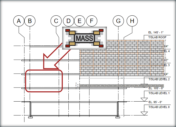
Use the Shear Wall Element Module to design each cross-section manually
The Shearline and Multi-Storey Shear Wall modules are available to save you time and speed up the design process!
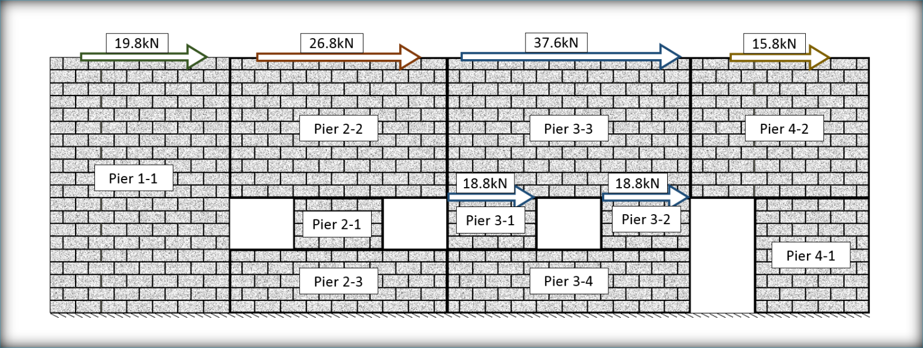
Designing a basic single storey elevation?
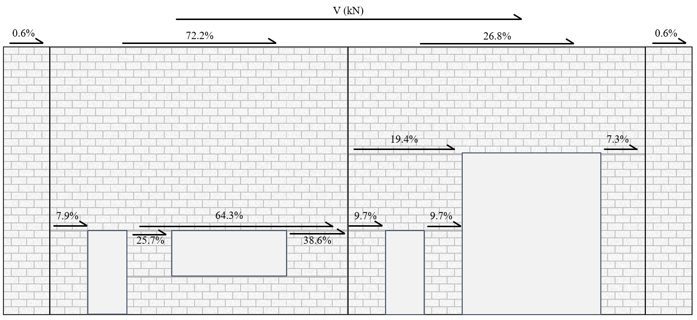
The load distribution calculation process of calculating and comparing relative pier rigidities can be confusing and time consuming. This is exactly what Shearline was created to address!
Designing a basic multi-storey elevation?
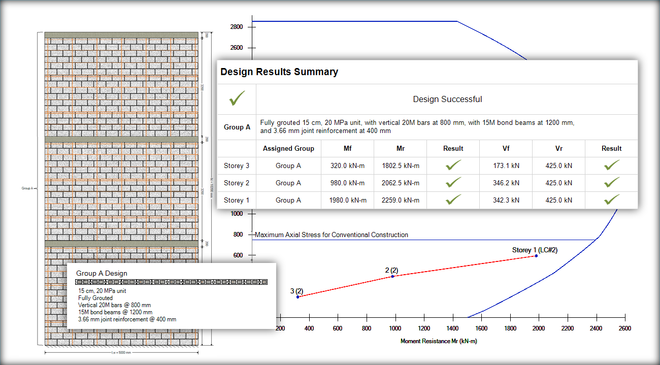
The Multi-storey shear wall module lets you model the wall and apply your loads in one convenient place.
In both cases, the software handles the menial load distribution process to create element designs for each pier without you having to manually create and model each element, one-by-one!
Learn More About the Tools Available for Designing Different Types of Shear Walls
Shear Wall Element
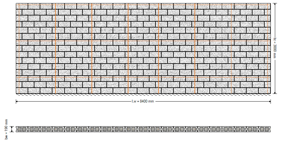
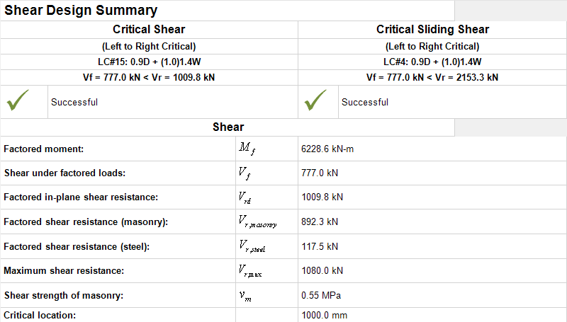
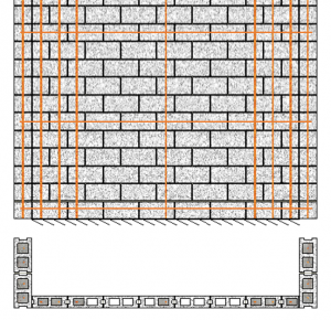
The shear wall module designs individual, solid sections of masonry shear walls based on the geometry and unfactored loads that are applied to that specific element, distributed and applied directly by the user.
MASS™ designs shear walls in accordance with CSA S304-14 Clause 7, 10, and 16, allowing for the following wall configurations:
- Unreinforced, ungrouted block masonry walls using hollow, semi-solid or solid units
- Unreinforced, fully grouted hollow and semi-solid block masonry
- Reinforced, fully grouted hollow block masonry and semi-solid block masonry
- Reinforced, partially grouted hollow and semi-solid block masonry
These shear wall configurations can be constructed using a considerable variety of masonry units. For shear walls, MASS™ supports the following block types: hollow, semi-solid, solid, half-high, half-block, and bond block. The default concrete block sizes available include 10, 15, 20, 25, and 30 cm units. The default block strengths include 15, 20, 25, and 30 MPa.
The support conditions available in the shear wall module include: fixed, fixed(R) and free, where fixed(R) specifies that the support condition is fixed in rotation, but not translation. Loadbearing shear walls are typically loaded laterally, parallel to the face of the wall, and are designed to resist both diagonal and sliding in-plane shear. Shear walls also experience axial loading which is taken into account when determining the flexural and shear dominated response of the element.
This version of the program allows the designer to specify flanges or boundary elements on both ends of the shear wall. Flanges or boundary elements must be fully specified in this version of the program.
Depending on the applied load, the support conditions, and the resistance of the masonry, or level of seismic hazard risk, a shear wall may or may not need to be reinforced. For shear walls that require reinforcement, up to two steel bars per cell can be placed. The program fixes the spacing of the reinforcing bars to the largest allowed by users and reduces this spacing if necessary to achieve a successful design, keeping with CSA S304-14: 10.15. The default steel bar sizes available include 10, 15, 20, and 25 mm nominal diameter bars. The additional seismic considerations of CSA S304-14: 16 are also considered when checking against minimum steel requirements.
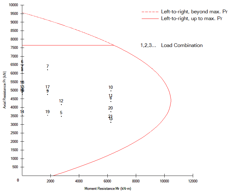
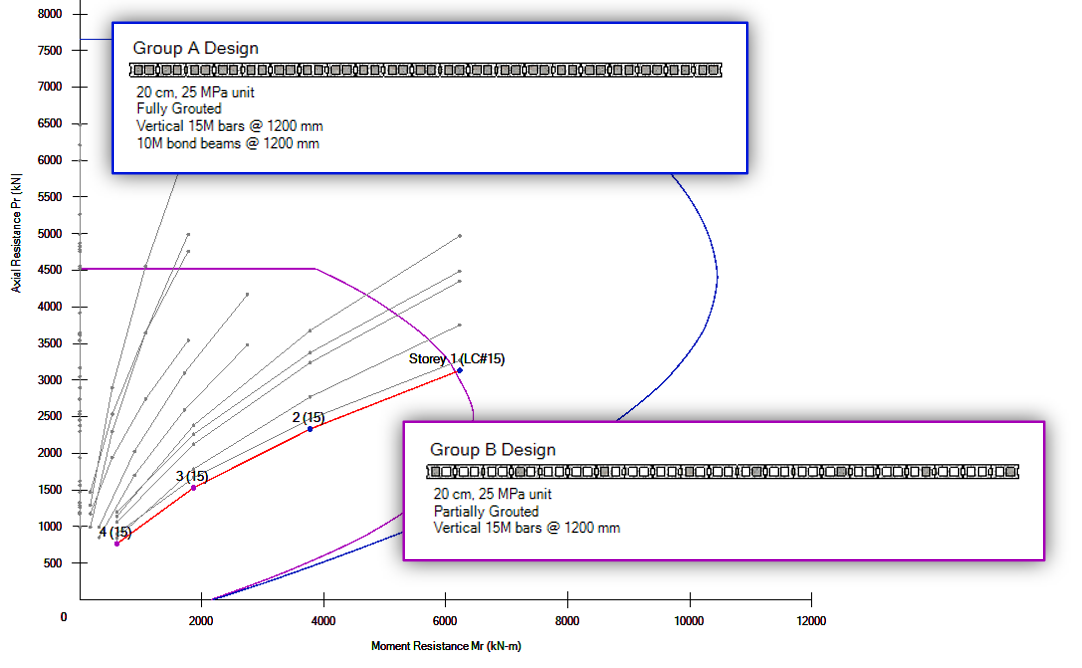
The shear wall module performs engineering calculations to design for the axial load and the moment, using the full length of the wall (not a per metre design). This design includes a detailed P-M diagram. In addition, the wall module provides shear design (which may include the addition of bond beams and/or joint reinforcement).
Learn More About Shear Wall Elements
Multi-Storey Shear Wall
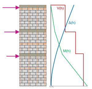
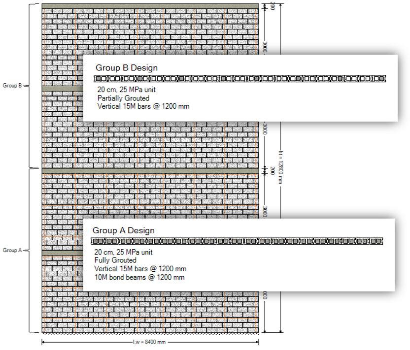
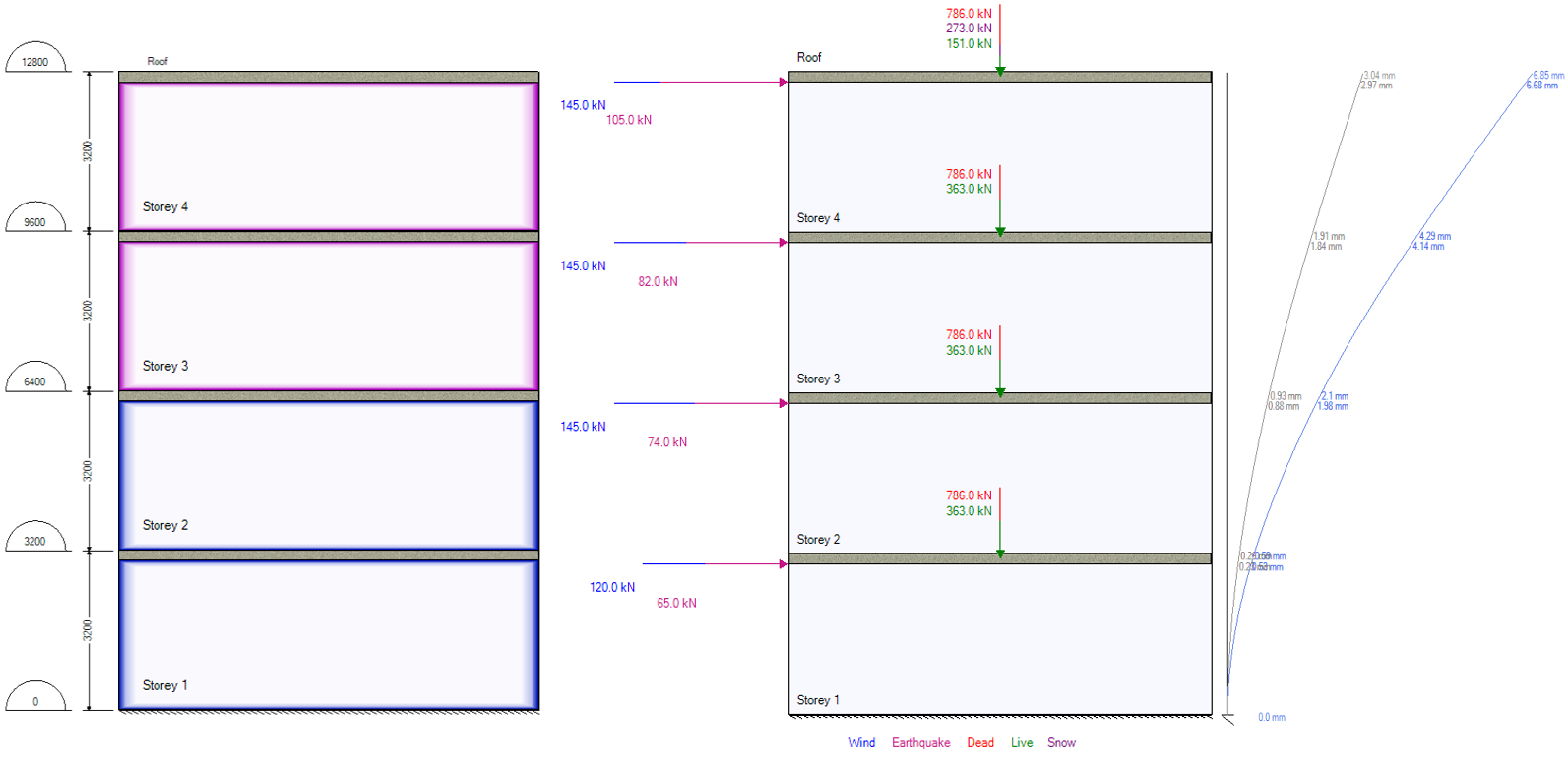
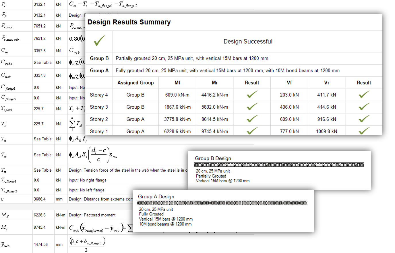
The Multi-Storey Shear Wall module allows for engineers to quickly specify floor locations, apply loads, and group designed sections to quickly and easily design vertically continuous sections of loadbearing walls.
By expanding the software’s scope to include an option for multi-storey design, this unlocks new possibilities for the types of calculations that can now be performed by MASS. In particular, by being aware of cross sections and effective stiffness values along the height, interstorey drift can be checked between floor slabs and ductility verifications can easily be performed.
Learn More About Multi-Storey Shear Walls
Shearline - for Single Storey Elevations
Shearline allows for users to design elevations containing openings and movement joints for combinations of vertical and in-plane loading.
The load distribution is done through the calculation of relative rigidities, performed for each designated pier and compared to determine which portions of wall resist the largest relative share of loads applied along the top length of the elevation.
Once the share of load resisted by each element has been determined, the software can then create a shear wall element for each area, send the distributed, unfactored loads, and await results. MASS can compare any number of designs before determining a masonry unit size and strength that will work for all cross sections.
